
Welcome To The Finite Lab-Transform
The Finite Lab-Transform (FLT)
The Finite Lab-Transform (FLT) is a number theoretical transformation applied to cryptographic computer operations, of which it is believed that Peter Lablans is the inventor. Certain applications of the FLT are protected by US Patents.
Number Theory
The FLT as explained herein is a technical invention to design and implement novel computer circuits/operations that may be used in cryptographic machines. One may consider the FLT also a Number Theoretical discovery. It is fairly unusual to discover a fundamental property like the FLT at this stage of Number Theoretical developments. Number Theory goes back for centuries. It is surprising for the FLT to show up now. To be fair, an FLT has no real meaning outside computer implementation and was pretty much useless pre-computers. The FLT was developed by Lablans as a technical solution to modify computer operations, not as a mathematical discovery.
What is the FLT?
The FLT is a transformation of a finite and discrete mathematical operation, such as a modulo-n addition or modulo-n multiplication. The FLT transforms the operation so that the output of the transformed operation is different from the original one. However, the meta-properties of the FLTed operation are identical to the meta-properties of the original operation.
What are meta-properties of an operation? An operation like an addition modulo-n is, in computer terms, a dyadic operation. It has two inputs (or input values) and a single output (or output value). The meta-properties of an operation are properties that apply to inputs and outputs, but do not necessarily determine actual input and output values.
Meta-properties of an operation are those that define for instance finite rings and finite fields in Number Theory or Abstract Algebra. Those properties also apply to computer operations, which are almost all finite by necessity.
Modulo-n Operations in FLT
For instance an operation may be commutative, so that a+b=b+a. Assume an FLT transforms the modulo-n + operation into an ⊕ operation. The ⊕ operation will also be commutative. Another property as expressed in (a+b)+c=(c+a)+b is that the + operation is associative. The ⊕ operation is also associative: (a⊕ b)⊕c=(c⊕a)⊕b.
Another property is the existence of a neutral element e, so that a+e=a and an inverse a-1 exists so that a+a-1=e, for every element a. We know e to be e=0. Under an FLT of + the ⊕ operation also has a neutral element with the properties a⊕a-1=p for every element a. However, the value of p after an FLT may be not 0.
Similarly a modulo-n multiplication has a zero element z, so that a*z=z for all values of a. In general z=0. Furthermore a neutral element k exists for which a*a-1=k. In general k=1. The inverse a-1 is called the multiplicative inverse of a. The FLT transforms operation * into ![]() . Operation
. Operation ![]() also has a zero-element, which may be element y, so that a
also has a zero-element, which may be element y, so that a![]() y=y for all a, but y may not be 0. Furthermore, an element q exists so that a
y=y for all a, but y may not be 0. Furthermore, an element q exists so that a![]() a-1=q, but q may not be 1.
a-1=q, but q may not be 1.
So, the meta-properties stay unchanged in an FLT, but the instantaneous values of certain properties may change in the FLT.
n-state invertible inverters
A next question is then: how is the FLT performed or realized? The answer to that question lies in the use of n-state invertible (or reversible) inverters and corresponding reversing inverters.
An inverter is a device (or an expression) with an input and an output that modifies the input to an output (or an input state to an output state.) An invertible inverter reverses the modification of the reversible inverter. A common and well known inverter is the binary inverter. The known binary inverter inverts an input state to its reverse state. State 0 is inverted to state 1 and state 1 is inverted to state 0. This binary inverter can be represented as [0 1]→[1 0].This representation has as benefit that its position (for instance position 0) also represents a state of an input or output. This notation says that state 0 is inverted to 1 and state 1 is inverted to state 0. The binary inverter [0 1] → [0 1] is identity as no modification takes place. The inverter [0 1] → [0 0] may be called “always off,” as the output is always 0, while [0 1] → [1 1] is “always on.”
An n-state invertible inverter is described by a sequence of n different n-state elements. The herein provided notation is:
[input sequence] → [output sequence].
For convenience the n states are defined as ranging from state 0 to state (n-1) and all states in between. A 7-state inverter for instance has states 0, 1, 2, 3, 4, 5 and 6. Again for convenience each state of an n-state inverter is provided with an index to indicates its position in the sequence. The identity 7-state inverter is [0 1 2 3 4 5 6] → [0 1 2 3 4 5 6]. Another reversible 7-state inverter is [0 1 2 3 4 5 6] → [1 2 3 4 5 6 0]. This says that input state 0 is modified to state 1; state 1 is modified to state 2, etc. and state 6 is modified to state 0. For reversible n-state inverters each possible state occurs exactly once in the output sequence. The input sequence is always [0 1 2 … (n-1)] and may be dropped. So instead of using [0 1 2 3 4 5 6] → [1 2 3 4 5 6 0], the notation 7-state inverter [1 2 3 4 5 6 0] may be used.
What is a state?
The term “state” may sound mysterious, but it is not. A “state” is merely a property that is assigned to a variable. The variable may be symbolic, as in mathematics. The variable may also be a physical property. Such as the “state” of an output of a circuit, or the “state” of a device. Assigning symbolic states such as numbers 0, 1, 2, …, (n-1) is merely for convenience. Usually, physical states do not come in convenient numbers. For instance, many people believe that computers process digits 0 and 1. Physically that is not the case. Computers commonly operate on signals with states LOW and HIGH, of which the values, or range of values, are explained in detailed data-sheets related to computer components.
Reversing n-state inverter
Each invertible n-state inverter invn has a reversing inverter rinvn. The meaning of such a reversing n-state inverter is that applying the reversing inverter rinv after applying invn creates the original starting state. For instance invn(k)=p provides rinvn(p)=k. Or rinvn(invn(i))=i. The above 7-state inverter inv7=[1 2 3 4 5 6 0] has as reversing inverter rinv7=[6 0 1 2 3 4 5].
How many reversible n-state inverters?
There are factorial n or n! reversible n-state inverters, including identity. That means that there are 3! or 1*2*3=6 different 3-state inverters. The number of permutations increases rapidly with n. There are 120 reversible 5-state inverters and over 40,000 reversible 8-state inverters.
How to perform the FLT
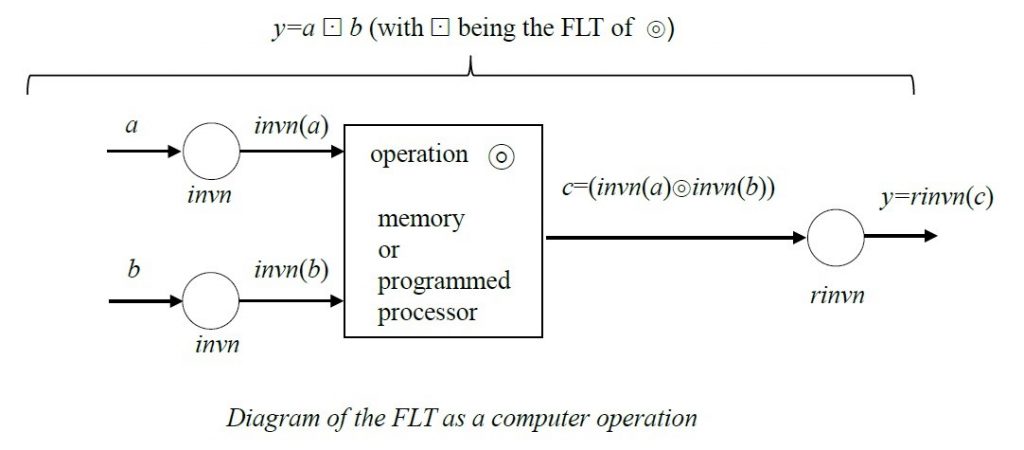
The FLT is applied to a dyadic (or 2-operand) operation (such as a modulo-n multiplication) in the following way. Represent the modulo-n operation by symbol ![]() , which may be a multiplication, an addition, a subtraction or any other dyadic operation. The input operands are a and b and the output is y. The operation
, which may be a multiplication, an addition, a subtraction or any other dyadic operation. The input operands are a and b and the output is y. The operation ![]() performs k
performs k![]() m=c.
m=c.
A reversible n-state inverter invn is obtained and its corresponding reversing inverter rinvn is determined.
The FLTed operation is: y=rinvn(invn(a) ![]() invn(b)), wherein c=invn(a)
invn(b)), wherein c=invn(a) ![]() invn(b).
invn(b).
The FLTed operation may be represented as: a![]() b=y
b=y
The operation ![]() has all the meta-properties of
has all the meta-properties of ![]() , though ordering of elements as well as zero-element and neutral element may have been modified.
, though ordering of elements as well as zero-element and neutral element may have been modified.
The FLT operation is applied in computer operations and may be represented in the form as shown below.
A Numerical Example
To illustrate the FLT a 7-state example using addition and multiplication modulo-7 will be shown below. One should keep in mind that a symbolic representation like (a+b) mod-7 in terms of a computer operation is identical to a representation by a switching or truth table in computer use.
The applied 7-state inverter is inv7=[2 3 4 0 5 1 6] with reversing inverter rinv7=[3 5 0 1 2 4 6].
The following figure shows the FLT of a modulo-7 addition based on inverter inv7

The neutral element (or zero-element) of the modulo-7 addition is 0: (a+0)=a mod-7. The additive inverse a-1 of a is determined so that
a-1+a=0. One can read from the original addition mod-7 table that the additive inverse of 1 is 6; of 2 is 5; of 3 is 4; etc. The FLT as illustrated above leaves the FLTed operation with the same meta-properties as the original operation. Name the FLTed operation ![]() . The additive zero-element is z, so that a
. The additive zero-element is z, so that a![]() z=a now is 3, as a
z=a now is 3, as a![]() 3=a for all a. This also modifies the additive inverses of
3=a for all a. This also modifies the additive inverses of ![]() . The additive inverse of 0 under
. The additive inverse of 0 under ![]() is 4; of 1 is 2; of 3 is 3; of 4 is 0; etc. One can see that
is 4; of 1 is 2; of 3 is 3; of 4 is 0; etc. One can see that ![]() is commutative, closed and has a zero-element and thus inverses. It is not directly clear that
is commutative, closed and has a zero-element and thus inverses. It is not directly clear that ![]() is associative. This can easily be checked exhaustively with a computer program. An example (4
is associative. This can easily be checked exhaustively with a computer program. An example (4![]() 5)
5)![]() 3=4
3=4![]() (5
(5![]() 3) and (3
3) and (3![]() 4)
4) ![]() 5 are all 6, as one can see from the
5 are all 6, as one can see from the ![]() table.
table.
The following figure illustrates the FLT of the modulo-7 multiplication based on inv7
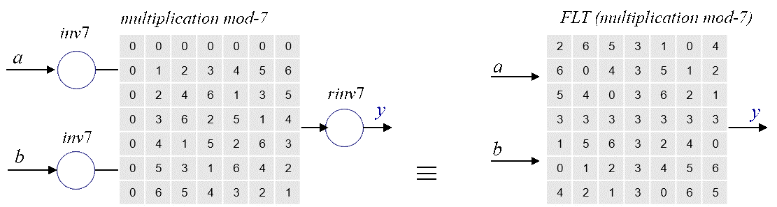
The zero-element of the multiplication mod-7 is of course 0 (a*0=0 mod-7). The zero-element z of the FLTed operation is 3. Name the FLTed multiplication mod-7 again ![]() . Then a
. Then a![]() 3=3 for all a as can be seen in the FLTed table. Furthermore, the neutral element e is so that a
3=3 for all a as can be seen in the FLTed table. Furthermore, the neutral element e is so that a![]() e=a is e=5. This means that the multiplicative inverse of element a under
e=a is e=5. This means that the multiplicative inverse of element a under ![]() has to be determined against:
has to be determined against:
a![]() a-1=5.
a-1=5.
Thus the multiplicative inverse of a=0 under ![]() is 2; of 1 is 4; of 2 is 0; etc. All meta-properties of * mod-7 apply to
is 2; of 1 is 4; of 2 is 0; etc. All meta-properties of * mod-7 apply to ![]() . application of certain dedicated algorithms such as the Extended Euclidean Algorithm (EEA). By applying the correct values of the neutral element one can apply the EEA to determine the correct multiplicative elements of a under
. application of certain dedicated algorithms such as the Extended Euclidean Algorithm (EEA). By applying the correct values of the neutral element one can apply the EEA to determine the correct multiplicative elements of a under ![]() . For small numbers of n as in modulo-n the multiplicative inverses may be determined from FLTed tables. This becomes impractical for n being very large and the FLTed EEA becomes more convenient.
. For small numbers of n as in modulo-n the multiplicative inverses may be determined from FLTed tables. This becomes impractical for n being very large and the FLTed EEA becomes more convenient.
The above 7-state FLT of a circuit modified in accordance with a 7-state inverter is illustrated in this video of a Matlab realization of the FLT.
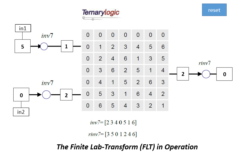
The above operational example of an FLT of a modulo-7 multiplication has been realized in a VBA program in a PowerPoint Presentation. It has been captured in a brief video that is activated by clicking on the above figure or by clicking here. A copy of the presentation can be obtained for free by sending a request to admin@ternarylogic.com. This program requires enablement of Macros to run properly.
Other functions that can be FLTed
As an example, operations modulo-n have been used to illustrate the FLT. This includes modulo-n with n being prime. A Finite Field is created when using addition and multiplication modulo-n with n prime. Other functions can also be FLTed. For instance operations over an extension finite field GF(n=qp) with q being prime can also be FLTed. This is explained for instance in US Patent 10,515,56. The FLT preserves also other properties such as “involution” or self-reversibility.
What the FLT is NOT
The FLT is not a bijection or straight-forward substitution. That is: not every state in the original table is transformed (as a bijection) into a same other state. For instance state 4 in the 7-state multiplication table is FLTed into state 5, 0, etc. depending on inputs. You can check this above in the example 7-state tables. Actually there may be several reactions to the FLT that are understandable, but still wrong. A) the FLT does not change anything because the reversing inverter changes the result back to the original. This is incorrect. B) The FLT is a bijection. This is wrong.
Where and Why to Apply the FLT?
The FLT can be applied in computer implemented methods, in error-correction, cryptography and random sequence generators, for instance. One important area of application is in cryptography such as encryption, PKI, authentication and digital signatures. The FLT, with its enormous amount of variation for even relative small values of n, make current cryptographic methods more secure with minimal change. It also allows for lightweight cryptography with small size parameters. See again US Patent 10,515,567.
The underlying idea is to apply proven and hard to attack cryptographic methods, and modify with the FLT one or more of the primitive computer switching functions. This approach is loosely based on the design methods as applied and taught by Dr. Gerrit “Gerry” Blaauw, with Amdahl and Brooks, co-architect of the legendary and impactful IBM System/360.
Blaauw/Brooks distinguish 3 levels of computer design: 1) the architecture (what a user sees); 2) the implementation (the logic design); and 3) the physical realization.
In a loose sense, this approach is followed in creating FLTed cryptographic applications. The data-flow or basic architecture of a cryptographic method such as AES, RSA, SHA-2 and DSS is maintained. However, the logic implementation is modified by FLTing certain switching functions. This renders the methods to be more unpredictable and thus more secure, without modifying the basic structure of a method.
In cryptography one may try increasing security by modifying (and usually increasing) parameters and parameter sizes or by adding random data (nonce). The FLT is a way to modify functions (that were considered to be immutable) without a need to increase size of cryptographic parameters, which can now even made smaller.
The Inventor
Peter Lablans is the inventor of the FLT. He has a Master’s degree in EE. He was a student of Prof. Blaauw and did work in Dr. Blaauw’s group on system design. Lablans is a prolific inventor and is the named inventor on over 50 patents.
The Patents
US Patents related to the FLT include: US 10,650,373; US 10,515,567; US 10,375,252; and US 8,577,026, all issued to Ternarylogic LLC. It is your own responsibility to check if an application of the FLT infringes the Ternarylogic patents. Additional cases are pending
Does that mean that you cannot apply or test the FLT? That is not the case. You have permission to apply the FLT for testing and educational purposes only and on a single machine only. You have no permission to apply one of our patent protected inventions for commercial and/or operational purposes. That is: no permission is granted to apply the patented inventions in and/or for exchange of data between two or more machines and/or to encrypt/decrypt data for storage on a single machine.
Contact us:
Please visit labcyfer.com for more information. Or contact us at info@labcyfer.com.